
3 Disc. Sim. of Cont. Systems
3.6.1 Direct realizationAll Activities
In a direct realization, the computer code implementing the different equation closely follows the form of the difference equation
$$y_k = a_1y_{k−1} + a_2y_{k−2} \optbreak{}+ b_0u_k + b_1u_{k−1} + b_2u_{k−2}$$
This is demonstrated in the code fragment shown below. The code fragment is written in C and is designed to run under freeRTOS, a free real-time operating system.
              01 // start of code fragment

              02float a1 = 0.0, a2 = -0.1716; // initialize transfer

              03float b0 = 0.2929, b1 = 0.5858, b2 = 0.2929; //   function coefficients

              04float y[3] = {0,0,0};  // initialize y values

              05float u[3] = {0,0,0};  // initialize u values

              06long int xLastWakeTime = xTaskGetTickCount();

              07int Ts = 5;   // sampling time in milliseconds

              08while (1) { // loop forever


              09u[0] = adc_in(); //Read input u(k)

              10y[0] = a1*y[1] + a2*y[2] + b0*u[0] + b1*u[1] + b2*u[2]; // compute y[k] using direct realization

              11dac_out(y[0]); // Write output y(k) to D/A converter

              12u[2] = u[1]; // Propagate variables

              13u[1] = u[0];// backwards

              14y[2] = y[1]; // for next

              15y[1] = y[0]; // sample

              16vTaskDelayUntil(&xLastWakeTime,Ts)// wait until the time for the next sample


17}
Use the Input control to change the input to the system in Figure 1. Use Step to step through the code one line at a time. The highlighted line will be executed after pressing Step The current value of the variables are shown as Variable Value.
u[1]=0.00
u[2]=0.00 y[0]=0.00
y[1]=0.00
y[2]=0.00
- What is the purpose of the code that starts in line 12?
- How many multiplication and additions must be implemented from the time the signal is read from the ADC to when it is outputs the value of $y_k$ at the DAC?
- How many multiplication and additions must be implemented from the time the signal is read from the ADC to when it is outputs the value of $y_k$ at the DAC if the code implemented a 3rd order difference equation.
In the code above the difference equation is explicitly calculated in line 10. While this approach is easy to follow, there is a potentially large computational delay between the acquisition of the input sample in line 09 and the writing of the output sample in line 11.
Also note the possibility of clock overrun in the line 16. If the code takes longer to execute than the sample time, Ts, the time allotted for the control
computation is too short.
3.6.2 Canonical realization
Consider the block diagram shown in Figure 2. Input $u$ and output $y$ are present, as are parameters $a_k$ and $b_k$.
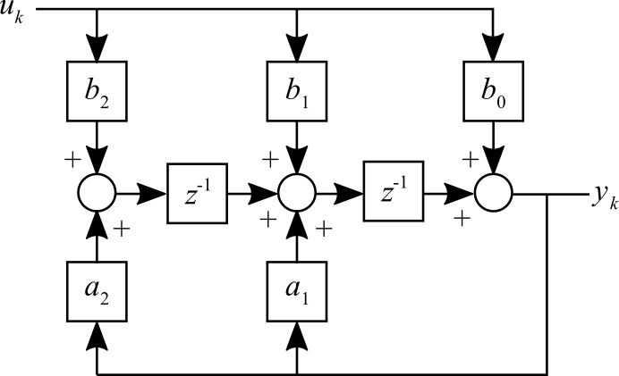
The computer code implementing the different equation using cannonical form is shown below. The code fragment is written in C and is designed to run under freeRTOS, a free real-time operating system.
        01 // start of code fragment

        02float a1 = 0.0, a2 = -0.1716; // initialize transfer

        03float b0 = 0.2929, b1 = 0.5858, b2 = 0.2929; //   function coefficients

        04float y = 0, u = 0;  // initialize y and u values

        05float x1 = 0, x2 = 0;  // initialize state values

        06long int xLastWakeTime = xTaskGetTickCount();

        07int Ts = 5;   // sampling time in milliseconds

        08while (1) { // loop forever


        09u = adc_in(); //Read input u(k)

        10y = x1 + b0*u; // compute y using cannonical realization

        11dac_out(y); // Write output y(k) to D/A converter

        12x1 = x2 + b1*u + a1*y; // Propagate variables

        13x2 = b2*u + a2*y;// backwards

        14vTaskDelayUntil(&xLastWakeTime,Ts)// wait until the time for the next sample


        15}
Use the Input control to change the input to the system in Figure 3. Use Step to step through the code one line at a time. The highlighted line will be executed after pressing Step The current value of the variables are shown as Variable Value.
u=0.00
x1=0.00
x2=0.00
- How many multiplication and additions must be implemented from the time the signal is read from the ADC to when it is outputs the value of $y_k$ at the DAC? Compare that to line 10 in the direct realization.
- How many multiplication and additions must be implemented from the time the signal is read from the ADC to when it is outputs the value of $y_k$ at the DAC if the code implemented a 3rd order difference equation - speculate.
- Where would quantization error occur in this system?
Although the program loop is shorter overall, note particularly that the computational delay between line 09 and line 11 is much shorter (see the activity questions) There is more computation after writing the output, but it’s not as critical there.